

Makerbot Replicator 2 Thermocouple Type Marlin Firmware
THIS POST IS A WORK IN PROGRESS
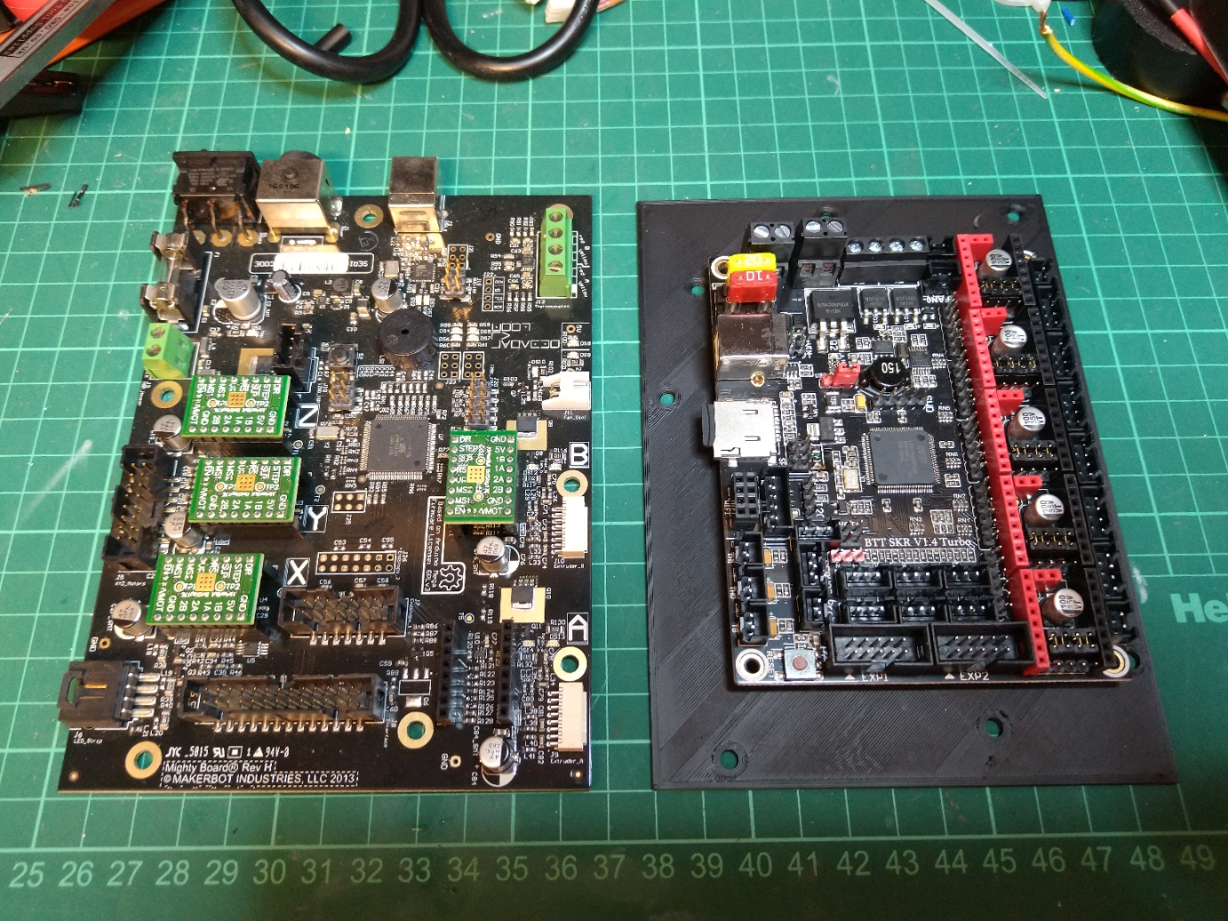
Concluding year I swapped the original mightyboard and botstep drivers from my replicator 2x over to a modern 32 chip board the bigtreetech SKR ane.4 turbo with 2.4″ TFT and converted it to a bowden setup.
Several people asked how and so I’m going to endeavour to write it it upwardly. I will keep to add to this every bit I get fourth dimension.

This is the basic process you need to follow if you want to do it like I have:
– remove mightyboard c/westward Botsteps
– remove LCD and mount
– remove original stepper motor wiring and replaced with generic ones.
– cut connectors off the endstops and re-crimp JST connectors on instead.
– fit 24vdc PSU under the bed
– fit BTT SKR in place of mightyboard with v x drivers (I used TMC2208s in standalone manner)
– add together TFT24 mount and LCD
– add excerpt fan to base
– add thermistor to bed in place of the Makerbot one.
– cutting remaining connectors and changed to JST.
– swap the the thermocouples for M3 thermistors (alternatively you can purchase a thermocouple board for the SKR)
– add mosfet for hotend fan control
– edit and compile marlin firmware.
Optional steps I undertook:
– Converted to Bowden setup by changing the extruders for E3D Titan extruders and the Hotends for an E3D V6 Chimera hotend.
– changed the LED strip over to NeoPixel.
– made new lid.
Parts list:
– JST Connector kit and Crimp tool.
– 4 10 1m and 1 x 0.25M HX2.54 NEMA stepper cables (4 pivot to 6 pin).
– 24vdc switchmode Power Supply.
– BTT TFT24.
– BTT SKR one.four Turbo c/w five x drivers (I used TMC2208s in standalone mode)
– Some wires.
– Assorted heatshrink.
– Clear acrylic for Lid.
– Some more wires.
Printed Parts I designed:
– BTT TFT24 Mount for replicator 2X
https://world wide web.thingiverse.com/affair:4552223
– Mightyboard rev h SKR one.four adapter
https://www.thingiverse.com/thing:4700179
– BLtouch mount
https://www.thingiverse.com/affair:4258034
– E3D Titan Mountain for Replicator 2X
https://www.thingiverse.com/thing:4463398
– E3D Chimera Mountain for Replicator
2X https://www.thingiverse.com/affair:4699838
– Hat comprehend parts
https://www.thingiverse.com/thing:4463425
– Octoprint Pi Bracket (Not finished)
I would recommend that you have the following tools handy:
– Soldering atomic number 26 & Solder
– wire cutters
– JST Crimpers
– Screwdrivers
– Allen keys

JST Connectors and crimping:
You lot volition apply allot of JST connectors if using the SKR turbo, information technology is actually of import that you lot practice crimping these and ensure you crimp the connectors well, I’one thousand using a cheap ratchet crimper and its pretty rubbish but with exercise I’ve managed to crimp the cables pretty well with them.
My conversion process explained:
Get-go job is one of the easiest parts of the process, remove all connectors from the the Mightyboard and then pull it c/w Botsteps from the standoffs in the base, remove the front door and front panel and so remove the LCD and mount.
Now yous tin can remove the original stepper motor looms and replace them with generic ones, I used 4 x 1m and ane 10 0.25M for the Z motor.
At this point you lot can mountain your PSU if yous are using an internal i, I chose to screw mine through the base under the bed with 4 10 M3 screws.
You tin can also mount the BTT TFT24 in the printed case now, this screws into the original mounting holes. Be sure to get the EXT connectors and the 5 pin ane in the correct order, I cut the black wires and crimped a JST connector on the smaller 1 to ensure that information technology couldn’t be reversed.

I mounted the BTT primary board using standoffs drilled through the bed base but I take subsequently designed an adaptor that you can spiral the BTT onto which then clips onto the original standoffs.
Once the new motherboard and TFT is mounted you can terminate the wiring, y’all’ll demand to cutting the connectors off the Endstops and from the bottom of the extruder/hotend looms.
The Hotend heater cables can exist wired directly into the board however the BTT SKR cannot read thermocouples without an additional board so I would swap them for M3 thermistors, you’ll need to crimp JSTs on the thermistor cables (Don’t worry virtually the polarity).
For the endstops you simply need one basis as these are joined on the PCB so just connect the 5v to VCC, Gnd to Gnd and sig to the indicate pin.
Equally the BTT SKR Turbo can simply control 1 fan, I added a Mosfet for the extruder fans (covered in
another postal service here) I likewise added an excerpt fan to the base of operations to pull warm air away from the motherboard and PSU paralleled to the output of the mosfet.
I found once completed that the bed thermistor read very depression, I call back this is considering of its placement within the silicone heat mat.
I added a new 100K thermistor in the heat bed with a bit of thermal compound and aluminium tape to hold it onto the back of the bed surface, this now reads very accurately.

Firmware:
Firstly I am non going to upload my consummate firmware as its irrelevant unless yous have literally the aforementioned setup as me plus If yous tin’t handle editing code and compiling it yous shouldn’t be doing this conversion.
Marlin isn’t complicated and I’grand non going into how to compile it but I volition aid with some useful snippets from mine.
Configuration.h //Original Hotend Offsets // First of the extruders (uncomment if using more than than one and relying on firmware to position when changing). // The commencement has to exist X=0, Y=0 for the extruder 0 hotend (default extruder). // For the other hotends information technology is their distance from the extruder 0 hotend. #define HOTEND_OFFSET_X { 0.0, 34.6 } // (mm) relative X-offset for each nozzle #define HOTEND_OFFSET_Y { 0.0, 0.00 } // (mm) relative Y-outset for each nozzle #define HOTEND_OFFSET_Z { 0.0, 0.00 } // (mm) relative Z-offset for each nozzle //=========================================================================== //============================== Endstop Settings =========================== //=========================================================================== // @section homing // Specify here all the endstop connectors that are connected to any endstop or probe. // Almost all printers will exist using 1 per axis. Probes volition use one or more of the // extra connectors. Leave undefined whatever used for non-endstop and not-probe purposes. //#define USE_XMIN_PLUG #ascertain USE_YMAX_PLUG #ascertain USE_ZMIN_PLUG #ascertain USE_XMAX_PLUG //#ascertain USE_YMAX_PLUG //#define USE_ZMAX_PLUG // Enable pullup for all endstops to prevent a floating state #define ENDSTOPPULLUPS #if DISABLED(ENDSTOPPULLUPS) // Disable ENDSTOPPULLUPS to ready pullups individually //#ascertain ENDSTOPPULLUP_XMAX //#define ENDSTOPPULLUP_YMAX //#define ENDSTOPPULLUP_ZMAX //#define ENDSTOPPULLUP_XMIN //#define ENDSTOPPULLUP_YMIN //#ascertain ENDSTOPPULLUP_ZMIN #define ENDSTOPPULLUP_ZMIN_PROBE #endif // Enable pulldown for all endstops to prevent a floating state //#define ENDSTOPPULLDOWNS #if DISABLED(ENDSTOPPULLDOWNS) // Disable ENDSTOPPULLDOWNS to set pulldowns individually //#define ENDSTOPPULLDOWN_XMAX //#ascertain ENDSTOPPULLDOWN_YMAX //#define ENDSTOPPULLDOWN_ZMAX //#define ENDSTOPPULLDOWN_XMIN //#ascertain ENDSTOPPULLDOWN_YMIN //#define ENDSTOPPULLDOWN_ZMIN //#define ENDSTOPPULLDOWN_ZMIN_PROBE #endif // Mechanical endstop with COM to footing and NC to Betoken uses "false" here (most common setup). #define X_MIN_ENDSTOP_INVERTING true // Set up to true to invert the logic of the endstop. #define Y_MIN_ENDSTOP_INVERTING true // Set to truthful to capsize the logic of the endstop. #define Z_MIN_ENDSTOP_INVERTING true // Ready to truthful to invert the logic of the endstop. #define X_MAX_ENDSTOP_INVERTING true // Fix to truthful to invert the logic of the endstop. #define Y_MAX_ENDSTOP_INVERTING true // Set to true to invert the logic of the endstop. #define Z_MAX_ENDSTOP_INVERTING true // Set to true to invert the logic of the endstop. #define Z_MIN_PROBE_ENDSTOP_INVERTING true // Set to true to capsize the logic of the probe. // @department machine // Invert the stepper management. Change (or reverse the motor connector) if an centrality goes the wrong way. #define INVERT_X_DIR true #ascertain INVERT_Y_DIR true #define INVERT_Z_DIR true // @section homing // Management of endstops when homing; 1=MAX, -1=MIN // :[-1,1] #define X_HOME_DIR 1 #ascertain Y_HOME_DIR i #define Z_HOME_DIR -one // @section machine // The size of the print bed #define X_BED_SIZE 235 #define Y_BED_SIZE 150 // Travel limits (mm) afterward homing, corresponding to endstop positions. #define X_MIN_POS 0 #define Y_MIN_POS 0 #ascertain Z_MIN_POS 0 #define X_MAX_POS 235 #define Y_MAX_POS 150 #define Z_MAX_POS 150
Configuration_adv.h #define E0_AUTO_FAN_PIN P1_00
